
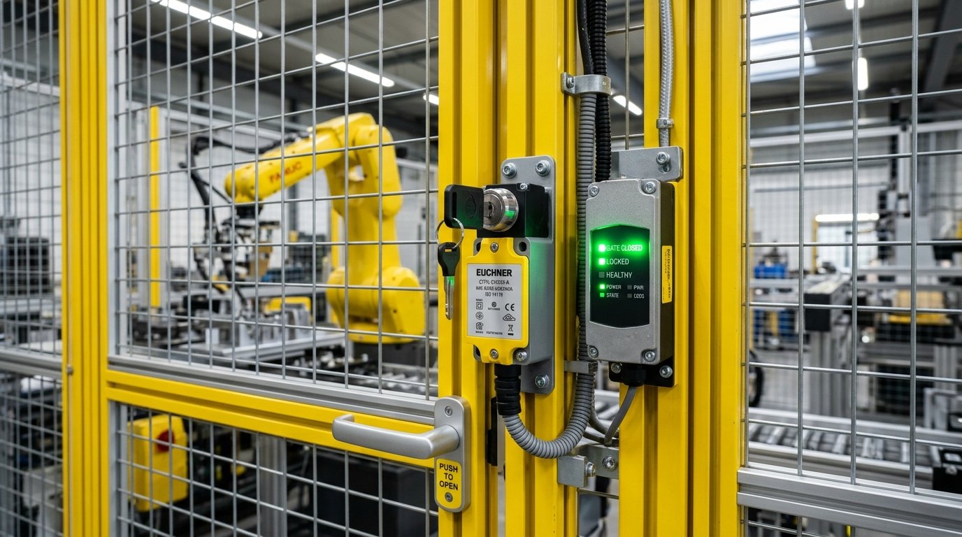
On the protective fencing of high-speed punch presses, robotic workstations, automated laser cutting machines, and large machining centers, safety guard doors serve as the final physical defense line safeguarding operators’ lives.
However, in actual factory operations, accidents related to equipment safety doors occur frequently: some happen because machine spindles maintain massive rotational inertia for tens of seconds even after power is cut, leading to severed limbs when operators open guards mistakenly; others occur because operators seek convenience and use tape or magnets to forcefully short-circuit standard safety limit switches to “cheat the system,” triggering severe industrial safety tragedies.
The International Organization for Standardization (ISO) has established the rigorous ISO 14119 international standard specifically for interlocking devices associated with guards.
Written specifically for machine safety architects, CE/UL certification compliance engineers, and EHS managers, this article provides an in-depth analysis of the core mechanical architecture, defeat prevention engineering design, and holding force (Fzh) physical design principles of solenoid interlocks complying with ISO 14119.
Core Requirements of ISO 14119: Why Standard Micro Switches Cannot Be Used as Safety Guard Door Locks
To cut costs, many small and medium-sized equipment manufacturers merely install an ordinary limit switch or reed sensor costing only a few dollars on the safety door. Under ISO 14119 regulations, this constitutes a critical compliance defect:
Lack of Ability to Prevent Defeat
ISO 14119 explicitly categorizes interlocking actuators into four types (Type 1 to Type 4). Standard switches belong to a low defeat-prevention level; an operator can easily bypass the switch using a screwdriver or any small metal piece, forcefully starting the machine while the safety door remains fully open. Compliant solenoid interlocks must feature high-level coded dedicated mechanical actuators or RFID integrated sensing to eliminate malicious human tampering.
Lack of Guard Locking Function
When dangerous inertial movements exist inside the machine (such as heavy flywheels, high-temperature molds, or residual high-energy laser beams), the system cannot merely achieve “cutting power when the door opens.” Instead, it must achieve: “Firmly locking the door via a robust mechanical structure until the hazardous energy has completely dissipated, ensuring no one can open it under any force!” This is precisely the irreplaceable regulatory boundary function of solenoid interlocks.
Mechanical Locking Principle Showdown: Power-to-Lock vs. Spring-to-Lock
Regarding the dynamic actuation method of solenoid interlock mechanisms, ISO 14119 strictly distinguishes between two main schools of thought, each applying completely different safety philosophies:
1. Spring-to-Lock / Power-to-Unlock — [Top Choice for Personnel Safety]
- Operating Mechanism: When the door closes, an internal high-rigidity mechanical spring automatically engages, firmly trapping the metal actuator bolt (mechanical self-locking); only when the machine confirms that dangerous motions have completely halted will the PLC energize the internal solenoid coil, using magnetic force to overcome spring resistance, retract the bolt, and allow personnel to open the door.
- Fail-Safe Characteristics: If the plant experiences a sudden blackout, electrical cabinet trip, or rat-chewed wiring, the locking mechanism remains firmly locked under the robust mechanical force of the spring! This guarantees that during the run-down period of high-speed rotating machinery, the safety door will never unlock due to power loss.
- Applicable Scenarios: All personnel safety perimeters involving high-inertia rotating spindles and robotic operating zones (highest priority recommendation under ISO 14119).
2. Power-to-Lock / Spring-to-Unlock — [Process Protection]
- Operating Mechanism: Power must be continuously supplied to the solenoid coil to maintain the door lock; once power is cut, the spring retracts the bolt to unlock the door.
- Characteristics and Limitations: The door will automatically open at the moment of power failure; therefore, in principle, it is strictly prohibited from being used alone to protect against high-risk personal injury.
- Applicable Scenarios: Only applicable to scenarios where no threat to human life exists but accidental door opening would ruin the production process (such as preventing dust ingress in semiconductor cleanrooms or heat loss in industrial ovens), or fire exit safety doors where egress pathways must remain unblocked during power outages.
High Holding Force (Fzh): How Does the Mechanical Structure Resist Violent External Pulling?
In real factory environments, operators in a rush or absentminded state often grip the safety door handle with both hands and pull violently. If the interlocking mechanism lacks sufficient mechanical strength, bolt breakage will directly expose personnel to danger.
According to ISO 14119, safety interlock mechanisms must be rated with strictly tested maximum holding force (Fmax) and rated holding force (Fzh):
Geometric Self-Locking and Lateral Shear Force Design
Premium solenoid interlocks incorporate quench-hardened alloy steel locking pins engineered with geometric self-locking angles to prevent back-driving. When external violent pulls reaching 1,000 N to 3,000 N (approx. 100 to 300 kg) are applied, the external force is converted into pure lateral shear stress across the metal pin, imposing zero axial load on the internal solenoid plunger.
Residual Magnetism Elimination and Anti-Sticking Mechanism
To prevent internal magnetically permeable materials from accumulating residual magnetism due to prolonged energization—which could cause the bolt to stick and fail to release after de-energization—Shih Shin Technology precisely positions non-magnetic stainless steel isolation spacers within the solenoid’s magnetic circuit. Paired with dynamic demagnetization return springs, this ensures 100% clean, crisp pin release within 50 milliseconds after power cut-off, completely preventing jamming-induced accidental door opening hazards.
ISO 14119 Safety Interlock Engineering Acceptance Specification Comparison Table
| Technical Parameter Metric | Spring-to-Lock | Power-to-Lock | Regulatory Boundary Requirement |
|---|---|---|---|
| Locking Power Source | Built-in mechanical high-rigidity safety spring | Continuously energized internal solenoid coil | Spring-to-lock type mandatory for personnel protection |
| Unlocking Power Source | Pulsed/continuous electromagnetic force overcoming spring | Automatic retraction by de-energized spring | Must incorporate fail-safe interlocking logic against power loss |
| Rated Holding Force (Fzh) | 1,500 N ~ 3,000 N | 1,000 N ~ 2,000 N | Verified via EN ISO 14119 static tensile testing |
| Manual Emergency Escape Switch | Equipped with mechanical emergency unlocking knob | No escape unlocking required (opens upon power cut) | Enclosed fencing interiors must be equipped with an escape release lever |
| Safety Contact Configuration | 2NC (positive opening safety contacts) | 2NC + 1NO auxiliary signals | Compliant with IEC 60947-5-1 direct opening symbol |
| Maximum Applicable Safety Level | Up to Cat.4 / PL e (ISO 13849-1) | Generally limited to Cat.1 ~ 2 / PL c | Must be paired with dual-channel safety relay monitoring |
Safety Interlocking Device Engineering Acceptance Standards and Test Checklist
After completing the installation of solenoid interlocks, machine safety design teams must conduct on-machine acceptance verification based on the following checklist:
- Standard 1: Physical Holding Force Test under Power-Cut Emergency Scenarios
- With the machine’s main power completely cut, apply a violent pull force of 1,000 N to the guard door. The mechanical bolt must remain locked without any metal cracking or door clearance exceeding limits.
- Standard 2: Positive Opening Verification of Safety Contacts
- Verify that when the door opens by 1 mm, the internal normally closed (NC) safety contacts achieve rigid physical disconnection driven by mechanical linkages without relying on any spring return, completely eliminating contact welding and short-circuit risks.
- Standard 3: Entrapped Personnel Emergency Escape Function Test
- Test the “internal emergency escape release lever” from inside the safety perimeter. When an operator pushes it internally with one action, the lock must mechanically force an unlock within 0.1 seconds and simultaneously send an emergency stop signal to the safety circuit.
Shih Shin Technology deeply understands the stringent safety standards of modern advanced automation equipment. Upholding design at Taiwan headquarters with manufacturing across Asia, all electromagnetic actuation and mechanical locking components undergo high-and-low temperature durability and impact tests, followed by 100% individual inspection across four electrical metrics before leaving the factory. If your machinery is undergoing CE certification or safety perimeter upgrades, feel free to collaborate with the Shih Shin Technology team to evaluate the most rigorous electromagnetic safety mechanism solutions.


