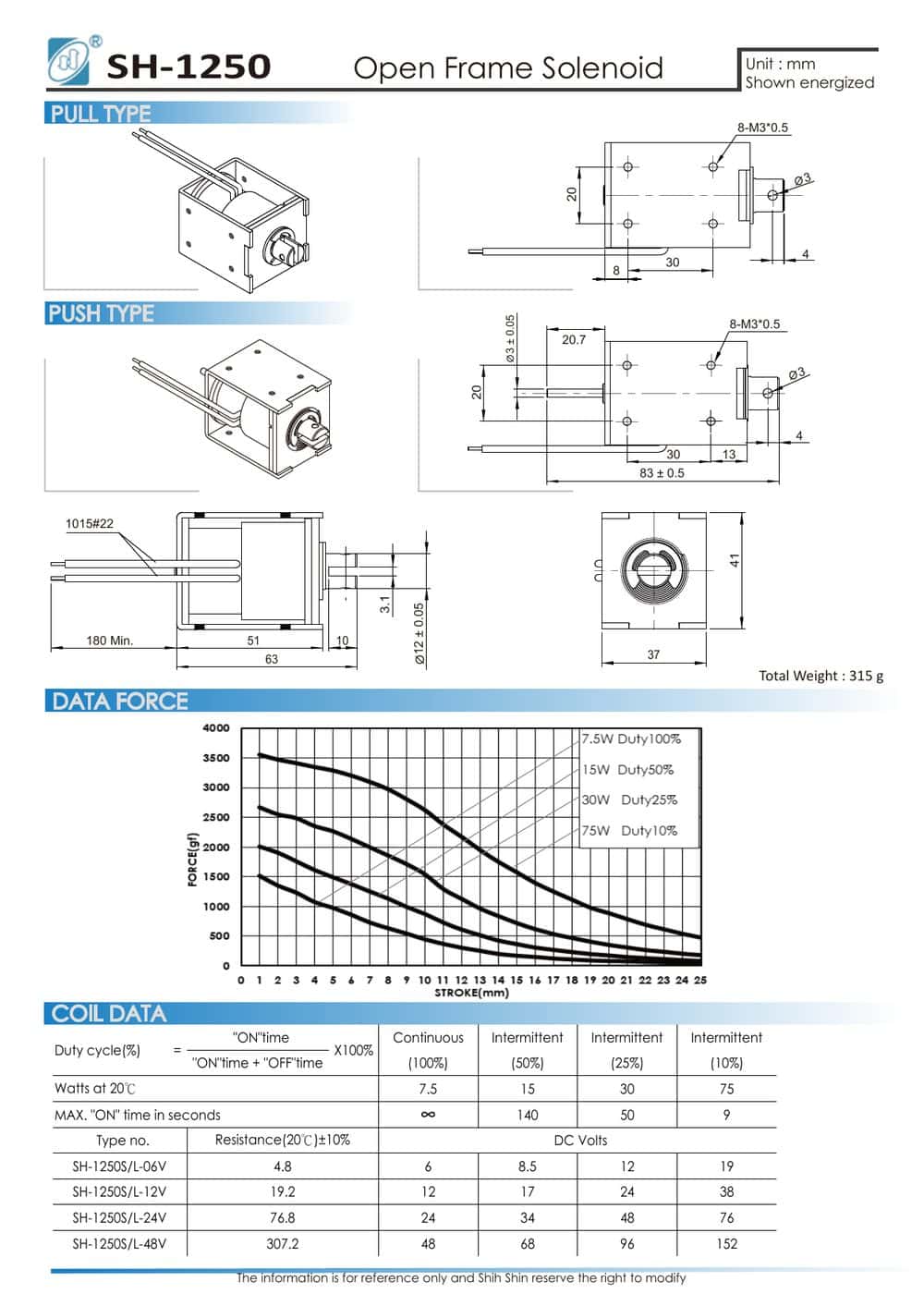
TL;DR: Open frame solenoids must be selected from the force-stroke curve, not a single catalog force number. Force peaks near the seated position and falls steeply with air gap: the SH-1250 delivers roughly 3500 gf at 1 mm of stroke on its highest-power (10% duty) curve and tapers toward zero at its full 25 mm stroke. Read force at your longest working gap, on the curve matching your true duty class. Duty cycle is a thermal limit with hard MAX ON times: the same SH-1250 runs 7.5 W continuously at 100% duty but 75 W for no more than 9 seconds per energization at 10% duty. Larger frames buy more continuous power and longer ON times; push versus pull is a load-path decision. Verify every selection against the manufacturer’s datasheet curve at operating temperature.

Catalog listings for open frame solenoids usually lead with a single force number and a wattage. Neither tells you whether the part will actually move your load. An open frame solenoid delivers very different force at different points in its stroke, and its power ratings come with hard limits on how long the coil may stay energized. This guide covers how to read the two charts that decide a selection, the force-stroke curve and the duty cycle table, and how to trade frame size against continuous operation. It is written for engineers specifying a part, not as a first introduction to solenoids.
Read the Force-Stroke Curve, Not the Headline Force
A solenoid produces its highest force when the plunger is nearly seated and the working air gap is smallest. As the gap grows, force falls off steeply. The SH-1250, a 315 g open frame unit with a 25 mm stroke, shows the typical shape: its curve runs from roughly 3500 gf at 1 mm of stroke on its highest-power (10% duty) curve down to almost nothing at the full 25 mm position.
The trap is that your load meets the weak end of the curve first. At the moment of energization, the plunger sits at the largest air gap of the cycle, exactly where force output is lowest. An engineer who sizes against the peak figure, or against an eyeballed average, builds a mechanism that hums, warms up, and never completes its stroke.
Three reading rules:
- Select at the working gap. Find the longest air gap your mechanism presents at the start of motion, draw a vertical line there, and read force off the curve at that point. That value, not the seated force, is what must exceed your load plus friction plus any return spring preload.
- Use the correct duty curve. Datasheets plot one curve per duty cycle rating. Higher duty classes drive the coil at higher watts, so the 10% duty curve sits highest on the chart, as it does on the SH-1250. Reading the 10% curve for a continuous application badly overstates your available force.
- Account for temperature. Published wattages are rated at 20°C. Copper resistance rises as the coil heats, current drops, and force drops with it. A curve read at room temperature is a best case, not a service condition.
Duty Cycle Is a Thermal Contract
The duty cycle ratings on a solenoid datasheet, typically 100%, 50%, 25%, and 10%, are thermal classes. They describe how hard you may drive the coil before the winding overheats. On the SH-1250, the four classes correspond to 7.5 W, 15 W, 30 W, and 75 W at 20°C. The frame is identical; only the drive level changes. The 6 V coil option measures 4.8 Ω, and 6 V across 4.8 Ω dissipates exactly the 7.5 W continuous rating. The higher classes are reached by overdriving the same coil for short periods.
Every intermittent class carries a MAX ON time, and it is a hard limit per energization, not an average. For the SH-1250: unlimited at 100% duty, 140 seconds at 50%, 50 seconds at 25%, and 9 seconds at 10%. Two consequences follow:
- Holding phases are continuous duty. If the mechanism must stay energized for minutes, only the 100% rating applies to that phase, whatever the long-term average works out to. This is where actuate-then-hold drive circuits, full voltage to pull in and reduced voltage to hold, earn their keep.
- The ratio alone is not compliance. A cycle can average 10% ON time and still violate the rating if any single ON period exceeds the MAX ON figure. Both conditions must hold: the duty ratio and the per-shot ON time.
Frame Size Sets Your Force and Heat Budget
Shih Shin’s open frame family covers 20 models, starting at the SH-0415, an 8 x 10 x 15 mm unit rated 0.8 W at 100% duty. Three points across the range show how the trade-off scales:
| Model | Weight | Power @ 100% duty (20°C) | MAX ON @ 50% duty |
|---|---|---|---|
| SH-0520 | 18 g | 1.6 W | 55 s |
| SH-1040 | 122 g | 4.2 W | 100 s |
| SH-1250 | 315 g | 7.5 W | 140 s |
Source: SH-0520 / SH-1040 / SH-1250 datasheets, Shih Shin Technology. Values are for reference and subject to design revision.
Two patterns matter. First, continuous power capability scales with frame mass: more copper and more iron dissipate more heat. Second, and less obvious, MAX ON times stretch as frames grow. At 50% duty the SH-0520 must de-energize after 55 seconds while the SH-1250 can hold for 140 seconds; at 10% duty the same limits are 3 seconds and 9 seconds. A bigger coil simply takes longer to reach its temperature limit. If your timing budget barely clears the MAX ON figure, moving up one frame size buys thermal headroom without changing the control scheme.
Compare mechanical envelopes and stroke options across the family on the industrial solenoid product range page before locking a frame size into your enclosure design.
Push or Pull: Decide by Load Path
Most open frame solenoids are built as pull types: energize the coil and the plunger retracts. A push version adds a pin through the backstop so the plunger’s motion is transmitted out the opposite end. Electrically and thermally the two behave the same; the selection questions are mechanical:
- Where do you need force strongest? A pull type used as a latch delivers its maximum force at the seated end of the curve, which suits hold-in-place work. If the demanding part of your cycle is at long gap, neither configuration escapes the curve; you size for the gap either way.
- Side loading. A push pin tolerates less lateral load than a plunger guided inside the frame. If the driven member can impose side force, keep the pin axial with a linkage, or reorient the mechanism to pull.
- Return method. Open frame units rely on an external return: spring, gravity, or the load itself. Return force subtracts from usable output across the whole stroke, so add it into the load figure you take to the curve.
A Selection Sequence That Survives Production
- Measure the real load: force to move the mechanism at its worst-case position, plus friction, plus return spring preload.
- Establish timing: single ON duration, cycle period, and ambient temperature. Derive the duty class from the ratio, then check the single ON duration against the MAX ON limit for that class.
- Shortlist frames whose curve, on the correct duty line, exceeds your load at your longest working gap with margin you can defend at elevated coil temperature.
- If you are replacing a part from another maker, run the numbers rather than trusting the label. The solenoid cross-reference maps common part numbers to comparable Shih Shin frames as a starting point; the curve check above confirms the match.
- Validate with a sample at your real voltage, temperature, and mounting orientation before tooling around the part.
All figures in this article come from measured datasheet values for the models named; how we source and check specification data is described in our editorial process.
Get a Curve for Your Duty Point
If you can state the load force, the working gap, the single ON time, and the cycle period, a model recommendation is a short exercise. Send those four numbers to info@solenoids.com.tw and our engineering team will reply with candidate frames and the matching force-stroke curves, typically within 24-48 hours on business days.
Frequently Asked Questions
Can I hold a solenoid energized longer at 10% duty if I give it extra off-time to cool down afterward?
No. MAX ON time is a hard per-energization limit, separate from the duty ratio. The SH-1250, for example, allows a maximum of 9 seconds ON at 10% duty (75 W drive) no matter how long the coil rests afterward. If a single ON period must run longer, drop to a lower-power duty class or move up a frame size, then re-read the force-stroke curve for that class.
The datasheet force looks more than enough, but my prototype stalls before completing the stroke. What am I missing?
You are most likely reading force near the seated position. Force falls steeply with air gap: the SH-1250 delivers roughly 3500 gf at 1 mm of stroke on its highest-power (10% duty) curve but tapers toward zero at its full 25 mm stroke. Read the curve at your longest working gap, on the line matching your true duty class, and remember published wattages are rated at 20 degrees C; a hot coil delivers less force.