TL;DR: The holding force on an electromagnet datasheet is measured at zero air gap, on flat machined low-carbon steel of full thickness, with a straight perpendicular pull. In service, paint, rust, surface roughness, thin sheet, and side loads each cut that figure, and the losses stack. Size against your worst-case surface and load direction, not the catalog number, and use the large steps between frame sizes as your margin. Shih Shin’s SH-ET series runs from the SH-ET2015 (Ø20 x 15 mm, 2 W, 2 kg rated) to the SH-ET7040 (Ø70 x 40 mm, 24 W, 120 kg rated, 100% ED). Validate with production parts, then email your application details for a sizing check.

A holding electromagnet is one of the simplest components on a BOM: a coil, a cup-shaped steel body, one machined pole face. That simplicity hides the most common sourcing mistake in this category. A buyer matches the catalog holding force to the load, orders samples, and then watches the magnet drop the workpiece at a fraction of the rated figure. The part is rarely defective. The rating was measured under conditions the application never sees.
This guide covers what the rated number actually means, which factors in your fixture decide how much of it survives, and how to size with enough margin to avoid a second sampling round. It uses the Shih Shin SH-ET holding magnet series as the working example; the full lineup, including tubular and frame-type solenoids, is on our industrial solenoid product range page.
What the Rated Holding Force Actually Means
Holding force on a datasheet is measured under reference conditions: the pole face mated flat against a machined low-carbon steel plate thick enough to carry the full magnetic flux, zero air gap, rated voltage on the coil, and a pull applied slowly, dead perpendicular to the face. Change any one of those conditions and the measured force drops. Change several at once, which is what a real machine does, and the losses compound.
Treat the catalog value as a ceiling. The engineering task is not to argue with the ceiling; it is to estimate how far below it your fixture operates, or better, to keep enough margin that the exact answer stops mattering.
Air Gap: Where Holding Force Goes First
The magnetic circuit runs from the pole face, through the workpiece, and back into the magnet body. Steel carries flux easily; air barely carries it at all. Any gap between pole face and workpiece inserts a high-reluctance layer into that circuit, and force falls steeply as the gap opens. The curve is steepest right at zero, which is why a part that almost touches holds far worse than a part that touches.
Air gap is not only the daylight you can see. In practice it includes:
- Paint and powder coat: non-magnetic layers with real thickness, sitting exactly where you need steel-to-steel contact.
- Rust, mill scale, and plating on the workpiece surface.
- Dust, chips, and oil film picked up in normal handling.
- Flatness error: a bowed sheet touches on a line or a point, and everything else is gap.
If your workpiece arrives painted, or the fixture cannot press the part flat against the pole face, assume that only part of the rated force survives and size for that condition.
Surface Finish, Plate Thickness, and Side Load
Surface roughness
A milled or flame-cut surface contacts the pole face on its peaks; the valleys are air gap. The rougher the mating surface, the smaller the true contact area and the lower the real holding force. A ground surface holds noticeably better than a saw-cut one for this reason alone.
Plate thickness and material
The workpiece is part of the magnetic circuit. Thin sheet saturates: once it cannot carry any more flux, additional flux produces no additional force, and a large magnet on a thin bracket behaves like a smaller magnet. Material matters the same way. Low-carbon steel is the reference; hardened, high-carbon, and many stainless grades carry flux poorly and hold less.
Side load
Rated holding force is a straight pull, perpendicular to the face. A load acting parallel to the face is resisted only by friction between pole face and part, and that friction capacity is far below the rated pull. If the part can slide, either add a mechanical stop that takes the shear, or size from the sliding case rather than the catalog number.
SH-ET Series Reference Data
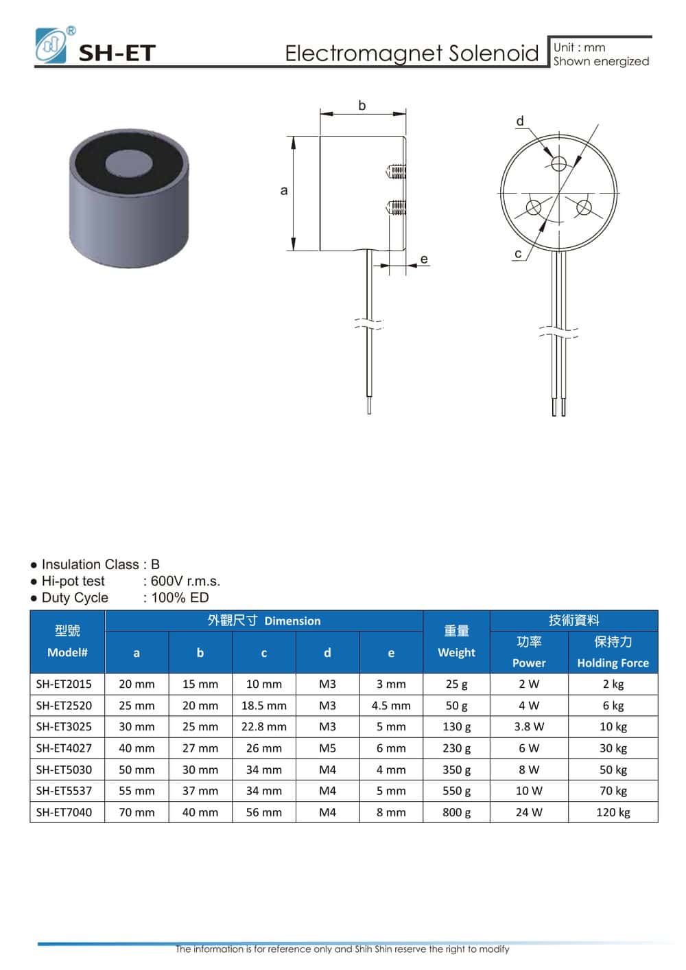
The SH-ET series covers seven frame sizes from Ø20 to Ø70 mm, spanning small fixtures through end-of-arm tooling. The SH-ET7040 datasheet also lists Class B insulation, a Hi-pot test at 600 V r.m.s., and 100% ED continuous duty.
| Model | Ø x H (mm) | Mounting thread | Weight | Power | Rated holding force |
|---|---|---|---|---|---|
| SH-ET2015 | Ø20 x 15 | M3 | 25 g | 2 W | 2 kg |
| SH-ET2520 | Ø25 x 20 | M3 | 50 g | 4 W | 6 kg |
| SH-ET3025 | Ø30 x 25 | M3 | 130 g | 3.8 W | 10 kg |
| SH-ET4027 | Ø40 x 27 | M5 | 230 g | 6 W | 30 kg |
| SH-ET5030 | Ø50 x 30 | M4 | 350 g | 8 W | 50 kg |
| SH-ET5537 | Ø55 x 37 | M4 | 550 g | 10 W | 70 kg |
| SH-ET7040 | Ø70 x 40 | M4 | 800 g | 24 W | 120 kg |
Source: SH-ET series datasheet, Shih Shin Technology. Values are for reference and subject to design revision.
We quote datasheet values as issued and flag anything we could not verify; the checks behind every published figure are described in our editorial process.
Sizing: Margin Beats Exact Derating
You can model gap and saturation losses, but on most fixtures the inputs (paint thickness tolerance, incoming surface condition, operator handling) are not controlled tightly enough for a precise calculation to be worth trusting. The practical method looks like this:
- Define the worst case. Heaviest part, dirtiest surface, largest credible gap, most off-axis pull, plus any vibration or acceleration the machine adds while moving.
- Pick a frame whose rating sits well above it. The steps between SH-ET frames are large: 10 kg (SH-ET3025) to 30 kg (SH-ET4027) to 50 kg (SH-ET5030). Use the step as your margin instead of trying to shave it thin.
- Check what the step costs. Power and heat scale with size: the SH-ET3025 draws 3.8 W, while the SH-ET7040 draws 24 W. In continuous holding that difference shows up in enclosure temperature and supply sizing. Weight matters on moving axes; 130 g against 800 g is a real difference on a fast pick-and-place arm.
- Validate with production parts. A ground lab plate confirms the magnet meets its rating. Only your actual painted, stamped, slightly bowed workpiece confirms the application works.
Holding Electromagnet or Permanent-Magnet Chuck?
Both hold ferrous parts against a face. The control behavior differs, and that difference usually decides the selection.
- Holding electromagnet: holds while energized, releases the moment power drops. Simple to control, fast to cycle, nothing mechanical to actuate for release. The trade-off: a power failure releases the load, so a part suspended over people or equipment needs a mechanical backup or a different architecture.
- Permanent-magnet chuck: holds with zero power and keeps holding through an outage, but needs a mechanical lever or an electro-permanent switching pulse to release. Suited to long static holds such as workholding on machine tools.
For automated lines that grip and release every cycle, the electromagnet is the natural fit; the 100% ED rating on the SH-ET7040 means its coil is designed to stay energized continuously at rated voltage. For safety-critical suspended loads, start from the failure mode, not from the force number.
Replacing a holding magnet on an existing drawing? Run the original part number through our solenoid cross-reference first to see whether it maps onto an SH-ET frame before you re-qualify anything.
For a sizing check against your real surface and load direction, email the load, mounting details, surface condition, duty cycle, and supply voltage to info@solenoids.com.tw. Our engineers typically reply within 24-48 hours on business days, either with a recommendation or with the questions we need answered before making one.
Frequently Asked Questions
The datasheet says 30 kg holding force, but my magnet drops the part at a much lower load. Is it defective?
Probably not. Rated force assumes zero air gap, a flat machined low-carbon steel surface at full thickness, and a straight perpendicular pull. Paint, rust, surface roughness, thin sheet, and side loading each reduce the real force, and the losses stack. Bench-test the magnet on a ground steel plate at rated voltage: if it meets its rating there, the fix is in the application, through surface preparation, clamping, or a larger frame, not in the part itself.
How much safety margin should I allow when selecting a holding electromagnet?
There is no universal factor, because the losses depend on your surface condition, air gap, and load direction. Define the worst case (dirtiest surface, largest gap, off-axis pull, vibration in motion), then choose a frame whose rated force sits comfortably above it. In the SH-ET series, the step from the SH-ET3025 (10 kg rated, 3.8 W, 130 g) to the SH-ET4027 (30 kg rated, 6 W, 230 g) is a small cost in power and weight for a large gain in margin. Confirm with production parts before release.