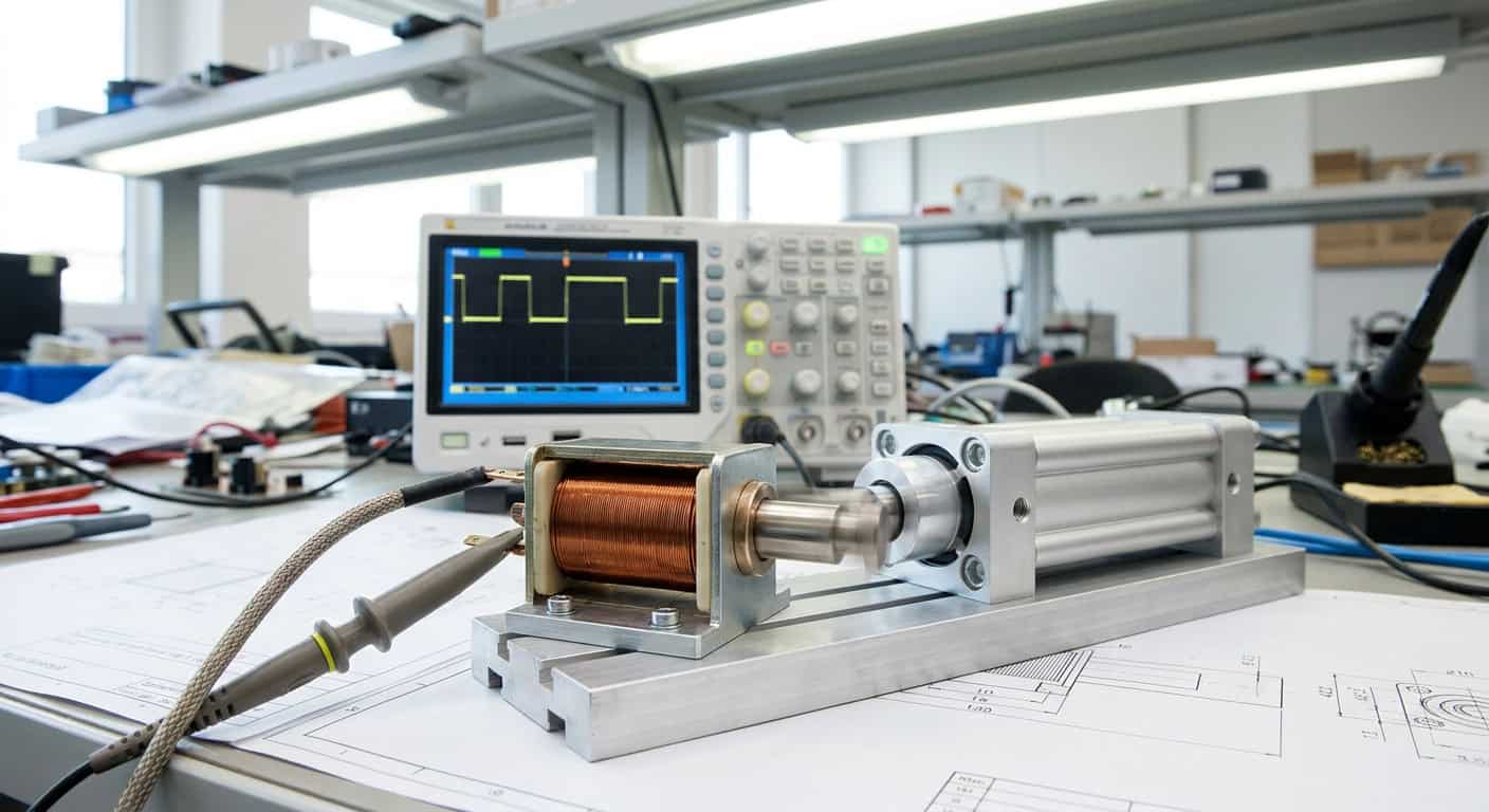
Many procurement and engineering teams often treat solenoids, solenoid valves, cylinders, and motor actuators as interchangeable thrust sources in the early stages of a project, but this intuition often collapses during dynamic testing. What isn’t apparent on paper is that when a mechanism needs to complete a 10mm reciprocating motion within 0.05 seconds, the high inertia of motor actuators and the air compression delay of cylinders will directly lead to system timing failures.
A reaction time of 10 milliseconds (ms) is the physical limit watershed for solenoids and solenoid valves, while cylinders typically require at least 50 milliseconds to overcome static friction at 0.6 MPa pressure. In high-speed dispensing or sorting equipment, if a cylinder is mistakenly used instead of a direct-acting solenoid valve, the production line speed will be forced to slow down to one-third of its original speed.
We must admit that while solenoids possess extremely fast reaction speeds, their force output curve is highly uneven, and the impact force at the moment of engagement is often accompanied by significant noise and wear. This ‘nonlinear output’ is a fatal flaw for solenoids in long-stroke applications; when the stroke exceeds 20mm, their holding force decays exponentially.
Control Boundaries in the Principles of Solenoids and Solenoid Valves
On the oscilloscope screen in the R&D laboratory, we can clearly observe the difference in inrush current between solenoids and solenoid valves at the moment of power-up. Solenoid valves essentially convert the electromagnetic force of a solenoid into the displacement of a valve core to control hydraulic or pneumatic pressure, whereas solenoids directly act on a Plunger to drive an external load.
The fluid pressure compensation design inside the valve body determines the opening speed of the solenoid valve; if the damping effect of fluid viscosity on the valve core’s movement is ignored, solenoid valves are highly prone to sluggish operation in low-temperature environments. In contrast, the movement of a pure solenoid is only limited by the inductance of the electromagnetic coil and the mass of the moving iron core; the operating environment’s temperature mainly affects coil resistance rather than physical resistance.
Engineering Insight: In systems with frequent on-off cycles, residual magnetism accumulation in solenoids can lead to release delays and must be physically isolated through demagnetizing air gaps or non-magnetic shims; otherwise, the mechanism will experience sticking failures after millions of operations.
Cylinder Force Calculation and Motor Actuator Comparison
When we require continuous thrust of over 500 Newtons (N) and a stroke of up to 300mm, should we choose a cylinder or a servo motor actuator? The answer to this question depends on your tolerance for positioning accuracy and energy efficiency. Cylinder force calculation is relatively simple, requiring only multiplying the piston area by the working air pressure, but the compressibility of the gas makes it almost impossible for cylinders to perform precise multi-point positioning mid-stroke.
Conversely, motor actuators (such as ball screw electric cylinders), despite initial setup costs being three times higher than cylinders, can provide micron-level repeatable positioning accuracy and programmable speed profiles. If a cylinder is likened to a direct train with only a start and end point, a motor actuator is a high-speed rail that can stop at any platform at will, with the trade-off being complex servo control algorithms and driver space.
| Characteristic Indicator | Direct-Acting Solenoid | Solenoid Valve | Standard Cylinder | Motor Actuator |
|---|---|---|---|---|
| Reaction Time | 2 – 15 ms | 10 – 50 ms | 50 – 150 ms | 50 – 200 ms |
| Positioning Capability | Two-position (Binary) | On/Off (Fluid Control) | Two-position (Sensor can be added) | Multi-point Precise Positioning |
| Maximum Stroke | Typically < 30mm | Depends on valve structure | Up to 1000mm or more | Up to 2000mm or more |
| System Complexity | Very Low (Direct Drive) | Medium (Requires air/liquid path) | Medium (Requires air source and solenoid valve) | High (Requires driver and encoder) |
Four Key Metrics for Evaluating Actuator Pros and Cons
A 24-volt (V) DC power supply is the most common driving voltage for these four types of equipment, but in terms of power management, latching solenoids and motor actuators have an inherent advantage. Latching solenoids use internal permanent magnets to maintain the engaged state after power-off, consuming instantaneous current only when switching states, which is fundamentally different from traditional solenoid valves that require continuous power to maintain valve position.
An unavoidable engineering compromise is that when systems face high-frequency vibration and high-temperature corrosive environments, the precise encoders and electronic components inside motor actuators are highly prone to failure. In such cases, structurally simpler cylinders or specially encapsulated solenoids exhibit extremely high survival rates, which is why heavy industrial sites still prefer traditional pneumatic components.
Inside a sealed enclosure where the ambient temperature exceeds 80 degrees Celsius, if the stroke is less than 10 millimeters, selecting high-temperature grade solenoids will result in over 200% higher reliability than motor actuators equipped with electronic encoders.
In a past production line upgrade case, improper solenoid selection stemmed from a misjudgment of load characteristics. For example, in an automatic door lock mechanism, if a cylinder is mistakenly used as a latch drive component, should the air pressure source fail during a power outage, the safety passage would immediately lock, a risk absolutely not permitted by fire safety regulations.
Decision Path for Solenoid Selection to Build High-Reliability Systems
Correct actuator selection should not only consider the price of a single component but must include the air preparation unit (FRL), piping, drivers, and subsequent maintenance costs in the overall cost of ownership calculation. Shih Shin Technology (世僖科技)’s approach in similar cases is to first evaluate the motion stroke and frequency; when the stroke is less than 20 millimeters and millisecond-level response is required, prioritize designing customized linear solenoids or direct-acting valves to simplify the system architecture and eliminate potential risks from air path leakage.
Is your equipment’s productivity affected by cylinder lag, or is it losing market competitiveness due to the high cost of motor actuators? Returning to their physical essence, solenoids, solenoid valves, cylinders, and motor actuators each have their irreplaceable golden application areas. Only by precisely matching stroke, force curve, and environmental resistance can the optimal balance between cost and performance be found.
It is recommended to provide the mechanism’s maximum load, duty cycle, and desired response time data during the initial design phase, allowing a professional team to conduct residual magnetism and temperature rise simulations to reduce post-debugging costs by over 30%.