The Physics of Air Gaps and Magnetic Circuits: Why Distance is the Arch-Nemesis of Attraction Force?
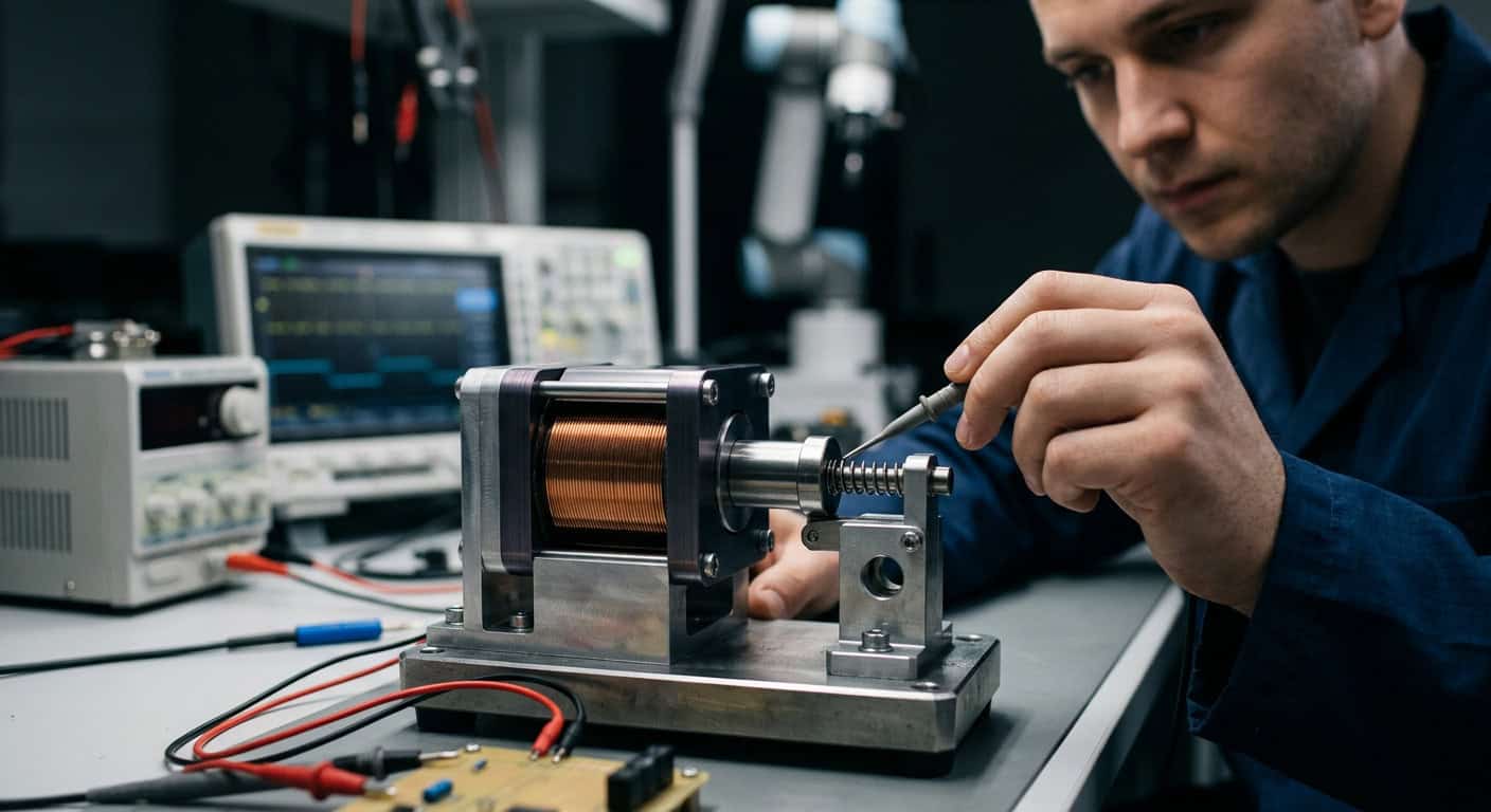
In the development process of automation equipment, engineers often encounter a phenomenon that is intuitively puzzling: even when stable voltage and current are applied, the force generated by electromagnets at different positions can vary vastly. The core of this nonlinear behavior lies in the changes in “Air Gap” and Magnetic Reluctance. When the electromagnet’s plunger is far from the stationary core, the space within the magnetic circuit is filled with air, and air has extremely low magnetic permeability, which means magnetic flux lines must overcome tremendous resistance to form a closed loop. According to physical laws, magnetic field strength is inversely proportional to the square of the distance, which explains why the force is weakest at the beginning of the stroke. As the plunger shortens this distance, the overall magnetic reluctance of the magnetic circuit rapidly decreases, the Magnetic Flux increases exponentially, finally reaching its peak the moment the two make contact. This characteristic determines that when a linear electromagnet grips or pushes a load, the difference between the initial force and the final force must be precisely calculated to avoid the predicament of being unable to move the load at the start or having excessive impact force at the end.
Performance Limits of Magnetic Reluctance and Permeable Materials
When we try to compensate for insufficient attractive force in long-stroke applications by increasing current, we often encounter the physical barrier of Magnetic Saturation. The arrangement of molecular magnetic domains in permeable materials is finite; once the material reaches saturation, even if more electrical energy is input, the incremental magnetic force generated will be negligible, instead converting into a large amount of waste heat, leading to an increase in coil resistance and generating Thermal Drift, further deteriorating the stability of the output torque.
In the large air gap phase, the core of the design lies in how to improve magnetic flux utilization; while in the small air gap phase, the core of the design shifts to precise control of magnetic saturation and residual magnetism.
How Does Plunger Geometry “Reshape” the Stroke Curve?
If we don’t want the attraction force curve to be so steep, how should engineers intervene? The answer lies in the geometric design of the contact surface between the plunger and the stationary core. The most common “Flat Face” design provides extremely strong holding force, but its attraction force diminishes very quickly with distance, suitable for short-stroke applications. In contrast, “Conical” or “Stepped Face” designs can change the angle at which magnetic flux lines pass through the air gap, by increasing the axial component of the magnetic field distribution, allowing the attraction force to behave relatively flatly over a longer stroke. This design is essentially a “power distribution” trade-off: we sacrifice ultimate holding force in exchange for a more stable and useful thrust in the middle of the stroke. Choosing the correct geometric structure can reduce mechanical impact during the operation of automation mechanisms and extend the system’s fatigue life. Below is a comparison of the performance of several common structures, which is crucial for initial model selection.
| Structure Type | Stroke Range | Attraction Force Characteristics | Typical Applications |
|---|---|---|---|
| Flat Face | Very Short (1-3mm) | Extremely strong end force, very weak initial force | Safety locking, electromagnetic brake |
| Conical Face | Medium to Long (5-15mm) | Flatter attraction curve, even distribution | Proportional valves, sorting levers |
| Stepped Face | Specific Stroke | Combines flatness and high holding force | Complex precision switching mechanisms |
Understanding the Interaction Between Duty Cycle and Thermal Equilibrium
When interpreting stroke curves, the impact of the Duty Cycle cannot be ignored. Although high-power electromagnets can provide impressive initial attraction force, if they cannot operate stably under Thermal Equilibrium conditions, as temperature rises, the increased resistance of the copper wire will lead to a drop in current, and the initially calculated attraction force curve will shift downwards. This is why, for long-stroke and high-frequency operations, we must allocate sufficient safety margin in the mechanical design, and not merely rely on the cold-state data from the specifications.
Customization Strategies for Extreme Stroke Requirements: Shih Shin Technology’s Engineering Philosophy
When standard products cannot meet specific industrial scenarios, the value of custom electromagnets becomes apparent. For example, in a high-speed automated production line, we might need an actuator with extremely fast response speed that still maintains high attraction force at a 10mm stroke; this requires multiple optimizations for coil winding density, magnetic circuit material, and pole tip geometry. Shih Shin Technology (Shih Shin Technology) in facing such challenges, it assists developers with simulation analysis to ensure that the electromagnet, under actual operating loads, its stroke curve can precisely match the resistance torque of the mechanical linkage. Many times, what engineers worry about most is the nonlinear variation of the attraction force making controller tuning difficult, rather than insufficient attraction force. Shih Shin Technology (Shih Shin Technology), with years of manufacturing experience, can minimize the negative effects of Hysteresis and Residual Magnetism through material treatment and precise tolerance control, providing customers with truly predictable actuation solutions. When considering next-generation product development, we recommend discussing with us how to reduce energy consumption and improve equipment stability by optimizing magnetic circuit structures.
Precisely matching stroke curves with load requirements is the first step to reducing mechanical wear and tear on equipment and improving precision.