
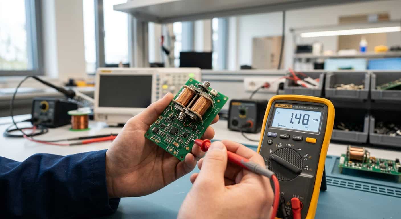
When planning handheld instruments, many engineers often only look at the suction force on static specifications, but overlook the accumulated power consumption under frequent operation, leading to equipment running out of power in less than half a day at the customer’s site.
More than 50% of power loss often comes from the continuous heat generation and unnecessary consumption of electromagnets when maintaining an engaged state.
We must admit that in a tight product development schedule, directly selecting off-the-shelf standard products is indeed the most convenient, but this means you must compromise with higher operating temperature rise and extremely short battery life.
The Most Common Power Consumption Traps When Selecting Low-Power Electromagnets
What isn’t visible on the drawings is that when a nominal 5W electromagnet is fitted into a sealed handheld testing instrument, after ten minutes of continuous operation, the internal temperature will rapidly rise above 65°C.
The logic behind this tolerance and temperature rise is that copper wire resistance increases with temperature, which in turn leads to a drop in current and a weakening of suction force, forcing the system to output more power to maintain operation.
The Invisible Cost of Static Suction Force and Dynamic Power Consumption
Can we only solve this endurance pain point by increasing battery capacity?
Compared to traditional electromagnets that require continuous power to maintain engagement, latching solenoids exhibit entirely different physical characteristics.
A 1-millisecond pulse current is enough to complete the state transition, with no energy consumption at all during the rest of the time.
While latching solenoids can significantly save power, their control circuits are relatively complex, and there is a tradeoff between holding force and response time, which is a technical compromise that must be faced during design.
Power Consumption Data Comparison Between Latching Solenoids and Traditional Electromagnets
It’s like securing an item with Velcro; force is only required at the moment of attachment and detachment, with no energy consumed while maintaining the state in between. This is the ingenuity of magnetic circuit design.
When a mobile device’s single operating cycle exceeds five seconds, abandoning the single-coil structure and adopting a dual-coil latching solenoid is the most direct and cost-effective design path to reduce the system’s static power consumption.
How significant is the power consumption difference between the two in actual test data?
| Operating Mode | Traditional Electromagnet (12V) | Unidirectional Latching Electromagnet (12V) |
|---|---|---|
| Instantaneous Startup Power Consumption | 4.8W | 4.8W (持續50ms) |
| Maintenance Power Consumption (Engaged) | 4.8W (持續通電) | 0W (maintained by permanent magnet) |
| Instantaneous Unlock Power Consumption | 0W (released by power cut) | 2.4W (reverse pulse 50ms) |
How Pulse Drive Circuits Optimize Mobile Device Battery Life
Traditional solutions connect DC power directly to the coil, while modern low-power solutions incorporate Pulse Width Modulation (PWM) control technology.
Full voltage is supplied within 100 milliseconds after activation to ensure smooth engagement, and then the duty cycle is reduced to 20% to maintain the position, thereby saving nearly 80% of the maintenance power consumption.
How to Avoid Residual Magnetism Interference and Ensure Precise Release of Low-Power Solenoid Valves
An unavoidable physical limitation is that when we introduce permanent magnets to save power, the issue of Residual Magnetism between the core and the armature becomes more challenging.
After disassembling samples that failed due to release delays, it’s often found that the tiny residual magnetic force is greater than the spring’s restoring force, preventing the valve from resetting in time.
The key to solving this problem lies in precisely adjusting the width and amplitude of the reverse demagnetizing pulse, or designing a Non-magnetic gap at the armature contact surface.
Key Decision Metrics for Evaluating High-Endurance Electromagnet Solutions
Facing the dazzling array of specifications on the market, how should procurement and R&D personnel establish a set of objective evaluation standards?
Compared to traditional methods that rely solely on theoretical calculations, Shih-Shin Technology (世僖科技)’s approach in similar cases is not to rely purely on theoretical calculations, but to reconstruct the magnetic circuit using simulation software and conduct dynamic power consumption tests at actual operating temperatures.
The 3 core evaluation steps include: first, confirming the true ratio of the Duty Cycle; second, evaluating the impact of ambient temperature on coil resistance; and finally, verifying the pulse width tolerance of the drive circuit.
While customized magnetic circuit design requires more testing time in the early stages, it ensures that the final product achieves optimal power savings without sacrificing reliability.
When the next generation of handheld devices gains market favor due to excellent power consumption design, it is these unseen magnetic circuit optimization details that are silently at work behind the scenes. Choosing low-power electromagnets not only saves battery life but is also a critical decision for improving the overall thermal stability and product lifespan of the equipment. Only by optimizing from the magnetic circuit source can mobile devices stand out in a fiercely competitive market.
It is recommended to provide operating frequency and expected battery capacity data at the initial stage of the project for accurate magnetic circuit simulation. This can save you at least 30% of later modification time.


