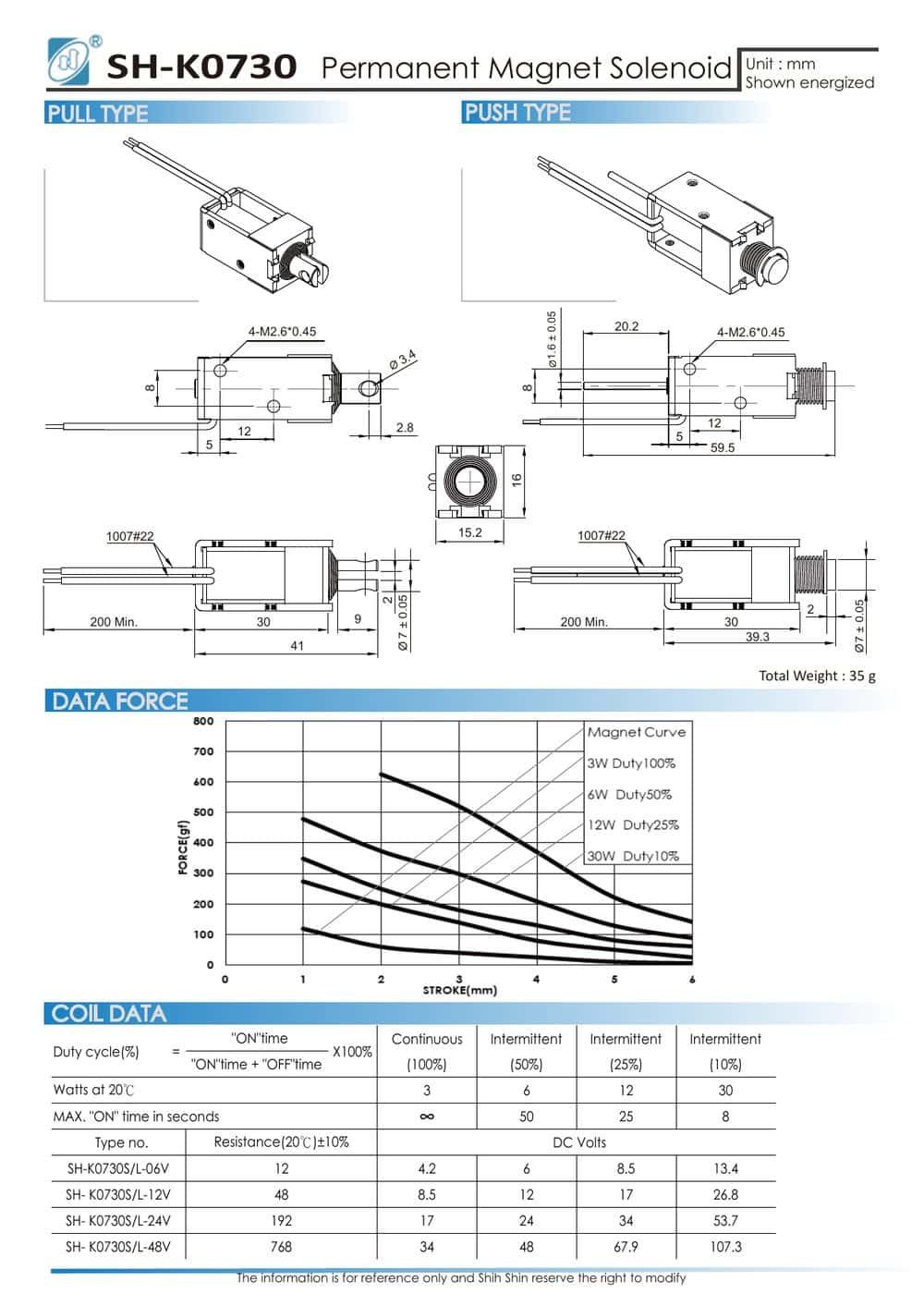
TL;DR: A latching (bistable) solenoid holds position with a permanent magnet, so coil power is zero during hold. You change state with a short current pulse and release with a reverse-polarity pulse, usually from an H-bridge. Design around three things: pulse width (just enough to complete the stroke), datasheet duty ceilings (the SH-K0730 allows 50 s ON at 50% duty, 25 s at 25%, 8 s at 10%), and power-loss behavior (the actuator keeps its last state, so fail-safe applications need stored release energy or a spring-return alternative). Shih Shin’s K-series covers seven latching models, from the 7.5 × 11 × 20 mm, 1 W SH-K0420 up to the SH-K1253, with the SH-K0730 offering 3 W to 30 W coil options.

A latching solenoid holds its armature with a permanent magnet instead of continuous coil current. Once the armature seats, you cut the drive and the part stays latched at zero power. That single property reshapes the drive electronics, the thermal budget, and the failure analysis of the mechanism around it.
Plenty has been written about why latching solenoids save energy. This guide stays on the implementation side: shaping the drive pulse, releasing reliably, reading duty-cycle limits, and deciding what your mechanism should do when the supply drops. Reference numbers come from the Shih Shin K-series, seven latching models from SH-K0420 through SH-K1253; the full lineup is listed in our industrial solenoid product range.
Zero-Power Holding: Split the Work Between Magnet and Coil
In a bistable latching solenoid, a permanent magnet sits inside the magnetic circuit. With the armature seated against the pole face, circuit reluctance is low and the magnet’s flux alone produces the holding force. The coil exists to change state, not to maintain it.
To latch, the drive pulse pushes coil flux in the same direction as the magnet’s. The combined field pulls the armature through its stroke; once seated, the magnet takes over and you switch the current off.
To release, you reverse polarity. Coil flux now opposes the magnet’s flux in the armature path, net force falls below the return spring or the load, and the armature drops out. The release window has two edges: too little reverse drive and residual attraction keeps the armature seated; too much, held too long, and some constructions pull the armature back in. Verify the window on the bench across your supply tolerance and operating temperature before you freeze the firmware constants.
Pulse Drive Circuit Design
Single-coil bistable types need polarity reversal, which in production means an H-bridge; a DPDT relay works for prototypes. Dual-coil versions trade the bridge for a second winding and two low-side switches. Either way, three parameters define the drive: amplitude, pulse width, and rest time.
Amplitude follows from the coil data. The 6 V winding of the SH-K0730 measures 12 Ω, so it draws 0.5 A and dissipates 3 W while the pulse is on (calculated from the listed coil values). Size the switches and the supply rail for that peak; there is no continuous rating to carry.
Set the pulse width to the shortest value that completes the full stroke under worst-case load at minimum supply voltage. Watch the coil current on a scope during bring-up: the armature seating shows up as an inflection in the current trace. Add margin past that point, then stop. Extra width buys heat, not force.
Treat the datasheet’s duty figures as thermal ceilings, not operating targets. The SH-K0730 lists a maximum ON time of 50 s at 50% duty, 25 s at 25% duty, and 8 s at 10% duty. The classic field failure is a firmware fault that parks the bridge in the ON state; protect against it with a hardware pulse timer or a capacitor-discharge drive that self-limits pulse energy. Clamp the inductive kick at turn-off with a TVS or diode network rated for the reversal scheme you chose.
Datasheet Reference: Three K-Series Frame Sizes
The table below shows the spread from a miniature frame to a configurable industrial unit. For a mid-range option, the SH-K0625 measures 13 × 15 × 25 mm at 2.5 W.
| Model | Dimensions / weight | Coil power | Duty / max ON time |
|---|---|---|---|
| SH-K0420 | 7.5 × 11 × 20 mm | 1 W | 100% duty (continuous rating) |
| SH-K0520 | 13 × 16 × 20 mm | 1.5 W | Refer to datasheet |
| SH-K0730 | 35 g (weight); dimensions per datasheet | 3 W / 6 W / 12 W / 30 W coil options | 50% duty: 50 s; 25% duty: 25 s; 10% duty: 8 s |
Source: SH-K0420 / SH-K0520 / SH-K0730 datasheets, Shih Shin Technology. Values are for reference and subject to design revision.
The power comparison against a conventional solenoid is a matter of structure, not just magnitude. A continuously energized part dissipates its rated coil power for the entire hold: energy equals power multiplied by hold time, and it grows for as long as the load is held. A latching type spends energy only during state changes: pulse power multiplied by pulse width, per actuation, with zero draw in between. For long hold times, battery supplies, and sealed enclosures with no airflow, that difference decides the architecture. The same 1 W that looks trivial on a lab bench becomes a permanent thermal load inside a sealed housing.
Fail-Safe or Fail-Secure: Decide the Power-Loss State on Paper
A latching solenoid retains its last state through an outage. That makes it neither fail-safe nor fail-secure by nature; it is state-retentive, and the system around it assigns the meaning. Run the consequence through each of the K-series’ listed applications:
- Fire door release: fail-safe behavior means the door must close on power loss. A latching holder needs a supervised energy reserve, typically a capacitor bank, that fires the release pulse when the supply drops. Without it you get zero standby power but no defined release.
- MRI and X-ray bed locking: state retention is the feature. The bed stays locked through a supply glitch, and the mechanism adds no coil heat and no continuous coil field during the hold.
- Sorting machines: high actuation rates push against the duty ceilings above. Budget the rest time between pulses, not just the pulse itself.
- Clutch assemblies: the clutch keeps its engagement state through a power interruption, which is either the requirement or the hazard. Your DFMEA decides which.
The decision rule: if the mechanism must assume a defined state when power drops, you have three options. Store release energy locally and fire it on supply loss, specify a conventional spring-return solenoid instead, or add a mechanical override. Write the chosen behavior into the requirements before schematic capture, not after the first field incident.
Before You Send the RFQ
Quote cycles run faster when the first email contains the numbers the applications engineer needs:
- Supply voltage and tolerance at the solenoid terminals
- Stroke and load force across the stroke, not just at seat
- Planned pulse width and drive topology (H-bridge, dual coil, capacitor discharge)
- Actuations per minute and worst-case burst pattern
- Ambient temperature range and enclosure airflow
- Required state on power loss
- Mounting envelope and lead or connector spec
If you are replacing an existing part, start from the part number instead: look it up in the solenoid cross-reference to find a matching K-series frame. All figures quoted in this guide come from manufacturer datasheets under our editorial process.
For sizing help or a datasheet package covering the full K-series, write to info@solenoids.com.tw with the checklist above. An applications engineer typically replies within 24 to 48 hours on business days.
Frequently Asked Questions
How long should the drive pulse be, and is it a problem if my firmware just leaves the coil energized?
Use the shortest pulse that completes the full stroke at minimum supply voltage under worst-case load, verified with a scope during bring-up. Leaving the coil energized is the most common field failure: latching coils are thermally rated for pulse duty, and the SH-K0730 datasheet caps ON time at 50 s at 50% duty, 25 s at 25%, and 8 s at 10%. Add a hardware pulse timer or a capacitor-discharge drive so a software fault cannot hold the bridge on.
If the power fails, does a latching solenoid release or stay locked?
It stays in its last latched state; the permanent magnet holds the armature without any supply. If your application needs a defined state on power loss, for example a fire door that must release, add a local energy reserve that fires the release pulse when the supply drops, or specify a spring-return solenoid instead.