
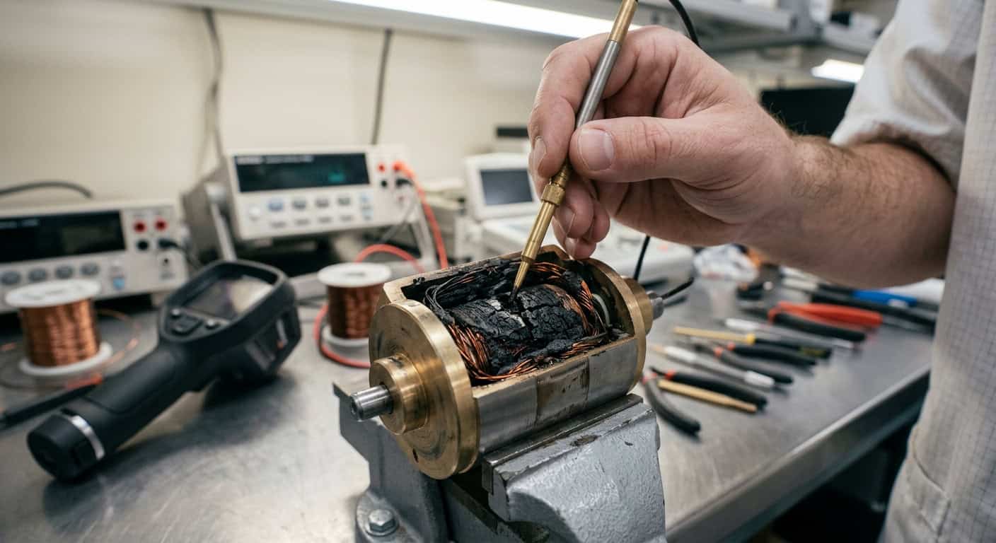
Many automation equipment performs normally during initial testing, but after being put into continuous operation on the production line for several months, frequent reports of coil burnout appear. When we investigate faulty machines on-site, opening the electromagnet casing often reveals a strong burnt smell, and the enameled wire has turned from its original reddish-copper to dark black, indicating that the internal insulation layer has already undergone thermal breakdown.
Analysis of Coil Burnout Causes: From Thermal Runaway to Insulation Breakdown
Why does the enameled wire inside the coil carbonize even when the input voltage matches the rated specifications on the label? The real key lies in the dynamic balance between heat generation and heat dissipation. When the coil is energized, Joule Heating rapidly accumulates, and if the heat cannot be transferred to the external environment in time, the temperature will continue to rise. Just like operating an engine in the high-RPM redline zone for a long time, if the cooling system cannot keep up with the heat generation rate, the melting of the insulated enameled wire is only a matter of time.
Compared to stable DC power supply, voltage spikes in the field environment are often the invisible killers that destroy insulation layers. When handling a packaging machine case, we found that due to the frequent starting of large motors in the factory power grid, momentary surges of over 600V were generated, which far exceeded the insulation withstand voltage limit that ordinary electromagnet coils can bear, leading to turn-to-turn short circuits between the enameled wires.
In a confined space where the ambient temperature exceeds 50°C, the heat dissipation efficiency of the electromagnet coil will significantly decrease. If a 100% duty cycle is maintained at this time, the internal hot spot temperature of the coil will exceed the Class B insulation limit within 30 minutes, leading to embrittlement of the insulation layer.
- Overvoltage Input: Long-term operation at over 110% of the rated voltage, leading to excessive current.
- Excessive Duty Cycle: Using an intermittent-type electromagnet as a continuous-type.
- Poor Environmental Heat Dissipation: Installation location is too narrow, lacking air convection.
- Frequent Operation: Extremely high-frequency switching generates excessive switching heat.
Key Design Points for Protection Circuits to Prevent Coil Burnout
Based on experience, when the operating ambient temperature increases from 25°C to 60°C, the coil’s heat dissipation efficiency decreases by approximately 35%, which directly compresses the system’s allowed duty cycle. To avoid this situation, engineers must incorporate active or passive protection mechanisms when designing drive circuits. Although many designers install fuses, the reaction speed of fuses is usually insufficient to protect fragile enameled wires from instantaneous high-voltage impacts.
When diagnosing a fault case, we found that the electromagnet generated an induced voltage exceeding 10 times the rated voltage at the moment of power-off, which was the culprit for breaking down the transistor and causing the coil to remain energized and burn out. Back EMF (Back Electromotive Force) is like the water hammer effect produced when a faucet is quickly turned off, causing a huge energy shock to the entire electrical system. To address this problem, connecting a flyback diode (Flyback Diode) in parallel across the electromagnet is the most basic defense mechanism. It provides a release path for the induced current, protecting the drive circuit and mitigating coil damage.
| Protection Component | Advantages | Disadvantages |
|---|---|---|
| Flyback Diode | Extremely low cost, simple structure | Slower energy release, may delay reset |
| TVS Transient Suppression Diode | Extremely fast response, high power absorption | Higher cost than diodes |
| RC Snubber Circuit | Can simultaneously suppress voltage and current change rates | Larger capacitor volume, requires precise parameter calculation |
Impact of Residual Magnetism and Induced Voltage on Coil Lifespan
When the current is cut off, the residual magnetic flux in the magnetic circuit, known as “residual magnetism,” can sometimes prevent the armature from quickly returning, leading to mechanical hysteresis. This hysteresis can cause the drive circuit to mistakenly believe the action is not yet complete and continue supplying power, thereby increasing the coil’s load. In precision control applications, we must consider how to eliminate the physical effects of residual magnetism through reverse pulses or by adding non-magnetic shims.
If the coil operates at high temperatures for an extended period, the insulation layer of the enameled wire will gradually age. For example, with the commonly used Class B insulation rating (130°C), for every 10°C increase in temperature, its insulation lifespan will be reduced by approximately half. Simply put, protection circuits are not just for surge prevention, but also for controlling the coil’s heat accumulation. If PWM (Pulse Width Modulation) technology can be used to reduce the voltage to the holding voltage (Holding Voltage) after the armature engages, typically only 30% to 50% of the rated voltage is needed, which can significantly reduce heat generation by over 70%.
Establishing Guidelines for High-Reliability Electromagnet Selection
When selecting an electromagnet, do you prioritize power or temperature rating? Shih-Shin Technology (世僖科技) in similar cases, the approach is to first accurately calculate the load cycle and the most extreme ambient temperature in the actual application, rather than just referring to standard laboratory data. We recommend incorporating a safety margin during the initial selection phase. For example, if the expected ambient temperature is 40°C, choose a Class F (155°C) coil, which is one temperature class higher, to provide stronger fault tolerance for the system.
The real key lies in an honest evaluation of application details. If the equipment requires frequent operation and has poor environmental ventilation, relying solely on diode protection is not enough; it must be combined with low-power drive design and high-grade insulation materials. Through reasonable circuit protection and precise physical parameter matching, the risk of coil burnout can be reduced to less than one in ten thousand, which is crucial for reducing maintenance costs and enhancing brand reputation.
Immediately check your electromagnet drive circuit, confirm whether a flyback component is connected in parallel, and measure the coil surface temperature after 1 hour of continuous operation, ensuring it does not exceed 80% of its insulation class limit.


