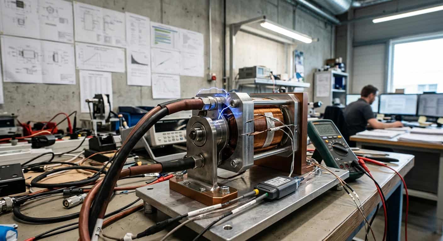
Many procurement managers, when accepting solenoids, often focus solely on the initial pull force values in the specifications, neglecting that “qualified” under laboratory conditions is different from “sound” after three to five years of operation in the field. What isn’t visible on the drawing is the physical degradation of materials under high temperature, high humidity, and high-frequency actuation. These subtle changes usually remain hidden in the first ten thousand cycles of standard testing but collectively erupt after the equipment warranty expires.
Baseline of Dielectric Strength Test Standards and Design Flaws
A continuous AC voltage of 1000V for 60 seconds is the most basic threshold for dielectric strength tests in most industrial-grade solenoids. This test is not merely to meet safety regulations but to verify the absence of pinholes or damage in the insulation layer between the enameled wire and the bobbin. If the test voltage is set only at twice the operating voltage plus 1000V, it might pass, but for equipment operating in high-humidity environments for extended periods, the molecular structure of the insulation layer will slowly degrade due to electric field stress.
Frankly, a single dielectric strength test cannot simulate the back EMF generated when a solenoid is frequently switched. When the coil is de-energized, if the protection circuit is not robust enough, reverse voltages of hundreds of volts will repeatedly impact the insulation layer. This is like continuously creating tiny vibrations on a dam; cracks may not be visible in the short term, but a dielectric breakdown three years later is predestined when the margin was insufficient during the testing phase.
Decisive Impact of Coil Temperature Rise Test on Insulation Class
Continuous energization at the rated voltage until the temperature reaches thermal equilibrium is the core of the temperature rise test. If the coil is designed at the edge of 130°C (Class B), and the test environment is only maintained at a normal temperature of 25°C, then when the end device is installed in a poorly ventilated enclosure and the ambient temperature rises to 50°C, the internal coil temperature will easily exceed the critical point of 155°C. This thermal stress accelerates the oxidation of the enameled wire’s insulation varnish, making it brittle and ultimately leading to inter-turn short circuits.
Dynamic Degradation and Material Fatigue in Solenoid Life Cycle Testing
Disassembling a solenoid that failed after five million operations, you’ll find that the problem is usually not in the coil but in the mechanical wear of the sliding parts. Standard life cycle testing typically requires 1 million to 10 million cycles under no-load or rated load. But the key is whether the actuation frequency during testing matches the actual application scenario. If the test involves 5 operations per second, while the actual application is 1 operation per hour, the inertial impact during testing might mask the oxidation and sticking issues that could occur in real-world use.
The true key lies in the hardness matching and surface treatment of the moving components. When the stainless steel plunger frequently collides with the guide tube, if the hardness gradient is improperly designed, tiny plastic deformations will occur on the metal surface. This not only changes the size of the air gap but also leads to variations in the residual magnetic flux. In highly precise automated production lines, this micron-level deformation directly manifests as fluctuations in actuation time, causing delays in otherwise precise gripping actions.
In high-temperature cycle testing, if the coil temperature rise exceeds 85% of the material’s insulation class, the aging rate of its insulation layer will increase exponentially. This is also the main reason for long-term failures that most standard tests cannot simulate in the short term.
Impact of Residual Magnetism Accumulation on Release Time
After a solenoid is de-energized, the residual magnetic flux in the magnetic circuit creates a persistent attractive force, known as residual magnetism. In the later stages of life cycle testing, as magnetic materials are repeatedly subjected to heat and mechanical stress, their hysteresis curve shifts, leading to increased residual magnetism. This causes a hidden failure: although the solenoid is de-energized, the plunger delays release or even jams completely due due to residual magnetism. This is a fatal risk in safety locks or precision valve applications.
Environmental Stress Screening Requirements for High Reliability
Imagine an automated gate operating in a coastal area, where the solenoid must face not only frequent switching but also salt spray corrosion. Environmental Stress Screening requires the solenoid to undergo 48 to 96 hours of spraying in a salt spray test chamber. If there are micropores in the surface plating, saltwater will penetrate and cause electrochemical corrosion, and the resulting rust spots will increase friction and eventually reduce the pulling force below the design standard. Such tests are not for “looks” but to verify whether the protective process can sustain the product throughout its entire life cycle.
- High and Low Temperature Cycle Test: Verifies the thermal expansion and contraction stability of materials under drastic changes from -20°C to +80°C.
- Vibration Resistance Test: Simulates whether coil leads will break due to fatigue during transportation or heavy machinery operation.
- Damp Heat Test: Verifies the retention rate of insulation resistance at 95% relative humidity.
- Load Characteristic Curve: Records the change in pulling force at different strokes to ensure sufficient margin after wear.
- Actuation Time Consistency: Monitors the deviation in release time after 100,000 continuous operations.
- Static Holding Force: Verifies the stability of magnetic circuit saturation during long-term energized states.
Salt Spray Test and Practical Standards for Corrosion Resistance
For solenoids exposed outdoors, the Neutral Salt Spray (NSS) test is an indispensable part. The standard requires that no visible red rust should appear on the casing and movable components after spraying. Simply put, this tests the compactness of the electroplating layer and the quality of the passivation treatment. If the galvanized layer thickness is less than 8 microns, or if the passivation solution ratio is imbalanced, the solenoid will experience sticking during operation in the first rainy season of actual service. This must be strictly quantified in testing standards.
Establishing Internal Solenoid Selection and Acceptance Criteria for Enterprises
When selecting, have you ever asked the supplier: under what load conditions was this life cycle test report completed? The performance of a solenoid is dynamic; a single data point cannot represent the whole picture. Shih-Shin Technology (世僖科技)’s approach in similar cases is to incorporate “residual magnetic release force” and “extreme temperature rise” into the mandatory items for Incoming Quality Control (IQC) for the customer’s specific application environment, rather than solely relying on the specifications provided by the original manufacturer. This acceptance standard, based on the logic of physical failure, can effectively filter out products that are “data-wise beautiful but short-lived.”
From another perspective, testing standards should not merely be a defensive line but a guiding principle for design. When residual magnetism exclusion mechanisms and insulation margins are considered during the R&D stage, subsequent testing will naturally flow smoothly. Instead of expensive after-sales maintenance after product failure, it is better to establish a stress testing system based on real-world conditions at the outset of selection. This is not only a manifestation of technical strength but also the foundation for a long-term commitment to end-users.
It is recommended to add a “continuous energization temperature rise test under 1.2 times the rated voltage” to the next solenoid procurement contract, and require that the insulation resistance must still be greater than 100MΩ after the temperature rise stabilizes. This can filter out 80% of potential quality hidden dangers.